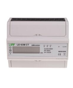
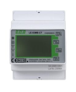
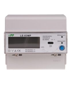
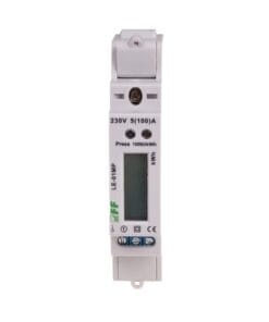
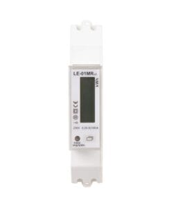
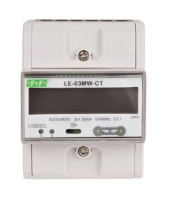
In the case of transformers with dedicated operating parameters, the meters display the actual value of the power consumed by the system.
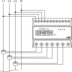
Functioning
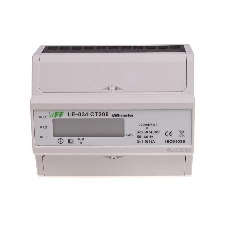
A special arrangement under the influence of the electronic flow of current and applied voltage in each phase generates pulses in proportion to the amount of electricity charged in that phase. Consumption of energy in the phase is indicated by flashing the corresponding LED (L1, L2, L3). The sum of the three phases of pulses indicated by flashing LED (800imp/kWh) is converted to energy, taken in the entire three-phase system and its value is determined by the segment LCD display.
Attention!
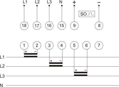
Meters are equipped with SO+ -SO- pulse outputs. It enables the connection of other pulse device (SO), reading the pulses generated by the meter.
The connection of additional device is not required for the proper operation of a meter.
*) Base current – determines the current value at which the percentage measurement error is close to zero. If the current flowing through the meter is higher than the base current value, then the measurement error is negative, which works to the benefit of the electricity payer. On the other hand, if the current flowing through the meter is lower than the base current value, the percentage measurement error is positive and that acts against the electricity payer. These statements arise from metrological characteristics (percentage measurement error as a function of current), supplied to the user manual of a electricity meter. It is obvious that the meter measures electricity correctly with the meter accuracy class in the whole measurement range.
Maximum current – the maximum current for permanent load of the electricity meter.
Minimum current – the lowest value of the load current, which the meter detects and record.
Marking on the device: 3×1.5(3×5)A – position 1 (before the parenthesis): base current of 3×1.5A; position 2 (in parentheses): maximum current 3×5A.


