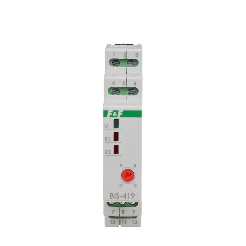
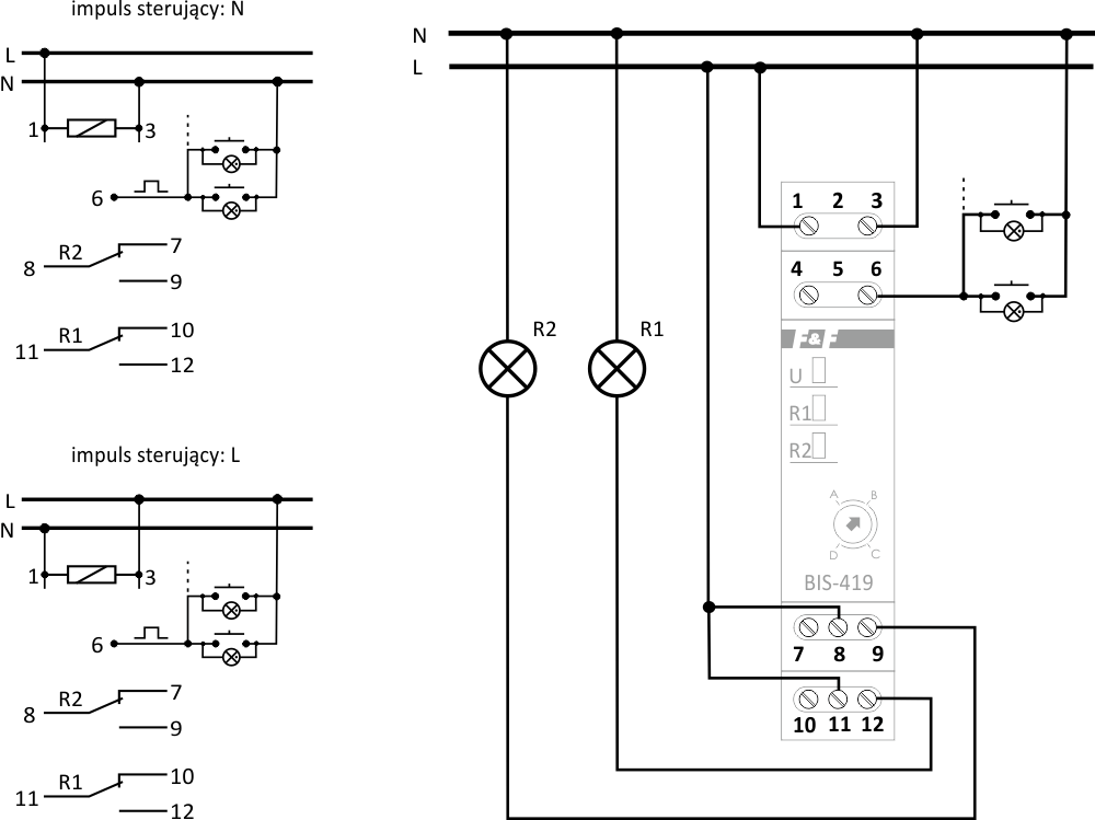
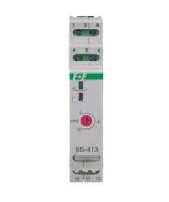
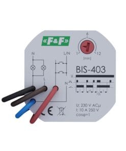
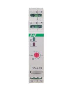
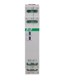
Electronic bistable pulse relay enables switching on or off the lighting or other device from several different points by means of parallel connected, momentary (bell) control switches.
The BIS-419 relay has two switching sections and enables two circuits (branches) of lighting or other receivers to be connected according to the selected sequence from several different points.
Functioning
Power supply of the relay is signaled by the green LED. The sequential relay has two separate outputs R1 and R2. The contact status (closed / open) is forced sequentially according to the given program. Switching the contacts into the next state follows the next pulse of the control button. Switching on contact R1 and R2 is signaled by lighting of the corresponding red LEDs R1 and R2. After a power failure, the contact status is reset. After restarting the supply voltage, the relay starts operation from sequence No. 0.
Work functions
Function A
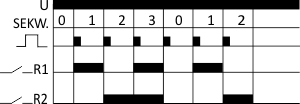
Subsequent presses of the button repeat sequence 0-3.
Function B

* Repeatedly pressing the button in less than 5 seconds, repeats sequences 1-3.
* The next pressing of the button after a time longer than 5 s, disconnects both contacts (sequence 0).
* Long press of the button – in any sequence – disconnects both contacts (sequence 0).
* After switching off both relays, pressing the button again restores the state before the shutdown (state memory). It does not apply to the case of power failure of the relay.
Function C
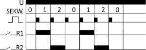
Subsequent presses of the button repeat sequence 0-3.
Function D

* Repeatedly pressing the button in less than 5 seconds, repeats sequences 1-3.
* The next pressing of the button after a time longer than 5 s, disconnects both contacts (sequence 0).
* Long press of the button – in any sequence – disconnects both contacts (sequence 0).
* After switching off both relays, pressing the button again restores the state before the shutdown (state memory). It does not apply to the case of power failure of the relay.
Tips
Illuminated buttons
Due to the low supply voltage, illuminated buttons should not be used. Maximum load current The contact current given in the technical data is the maximum value and may be subject to restrictions – more information. If the information provided indicates that the relay in the device is insufficient, it is recommended to use an external switching element (e.g. contactor) adapted to switch large surge currents.State memoryThe relay does not have a “memory” of the contact position. This means that after the power supply is switched on, the relay contact will always remain in the off state. Resistance to surge currents The device uses an “inrush” type relay characterized by high resistance to short-term surge currents generated, for example, when switching on LED lamps, ESL fluorescent lamps, electronic transformers, discharge lamps, etc.


