Compliance
MID Directive 2004/22/EC
EN 50470-1/3
Functioning
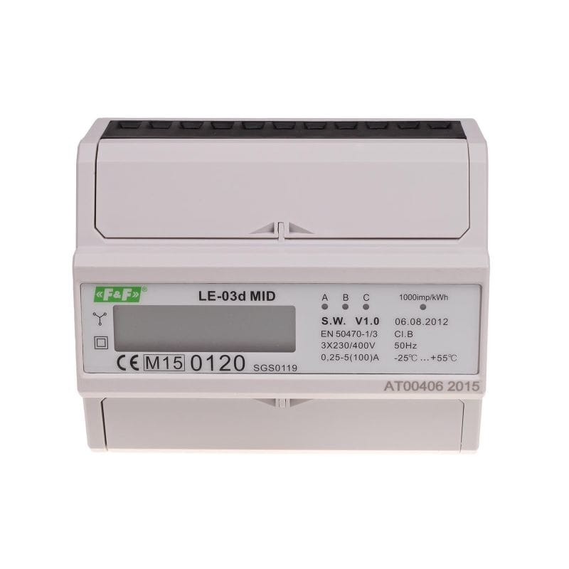
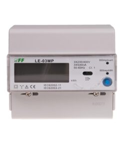
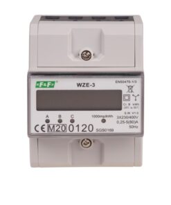
A special electronic system under the influence of flowing current and applied voltage in each phase generates pulses proportional to the energy drawn in the respective phase. Energy consumption in the phase is indicated by a flashing of corresponding LED (A, B, C). The sum of the three phase pulses is indicated by a flashing LED and converted into energy absorbed throughout the three-phase system. Its value is displayed by the segment LCD display. The fractional digit represent the decimal (.1 kWh = 100Wh).
Attention!
The meter is equipped with pulse output SO+ – SO-. This allows you to connect another pulse device (SO) that reads pulses generated by the meter.
No additional connected equipment is required for proper operation of the meter.
*) Base current – determines the current value at which the percentage measurement error is close to zero. If the current flowing through the meter is higher than the base current value, then the measurement error is negative, which works to the benefit of the electricity payer. On the other hand, if the current flowing through the meter is lower than the base current value, the percentage measurement error is positive and that acts against the electricity payer. These statements arise from metrological characteristics (percentage measurement error as a function of current), supplied to the user manual of a electricity meter. It is obvious that the meter measures electricity correctly with the meter accuracy class in the whole measurement range.
Maximum current – the maximum current for permanent load of the electricity meter.
Minimum current – the lowest value of the load current, which the meter detects and record.
Marking on the device: 0.25÷10(100)A – position 1 (before the parenthesis): base current of 0.25÷10A; position 2 (in parentheses): maximum current 100A.


