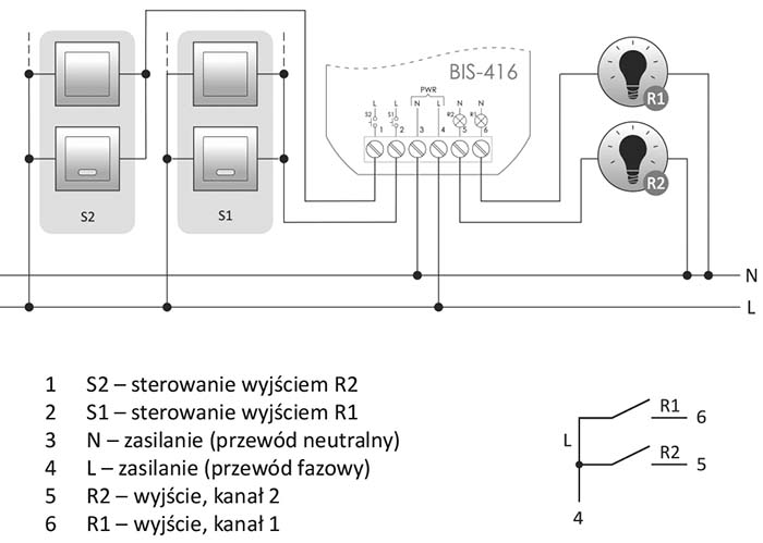
Operation
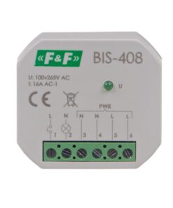
The relay is activated with a current pulse caused by the press of any momentary (bell) button connected to the relay. Subsequent pulse will switch the relay off.
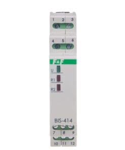
The relay has two independently controlled channels.
Control is carried out by means of two separate signal inputs. Pulse on S1 input controls the R1 output. S2 input and R2 output operate on the same basis.
The relay does not have a “memory” of the contact position, i.e. when power returns after power failure, contact of the relay will be set in the disabled state. This prevents automatic switching of controlled receivers without supervision after prolonged power outage.
NOTE!
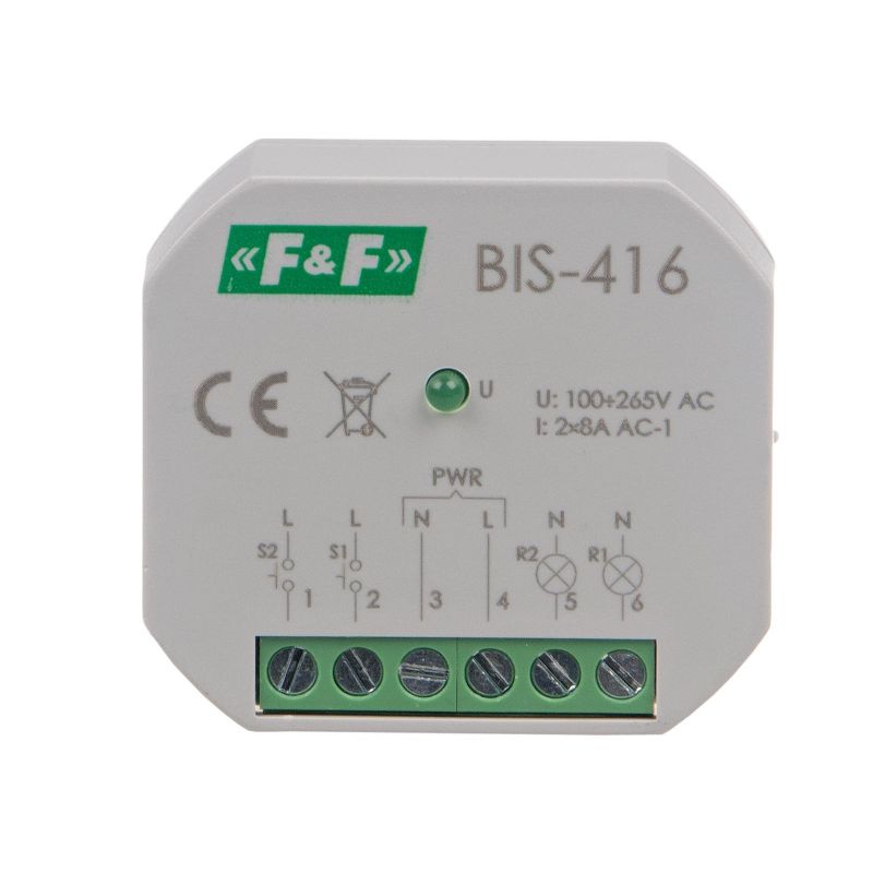
BIS-416 is compatible with backlit buttons. ![]()
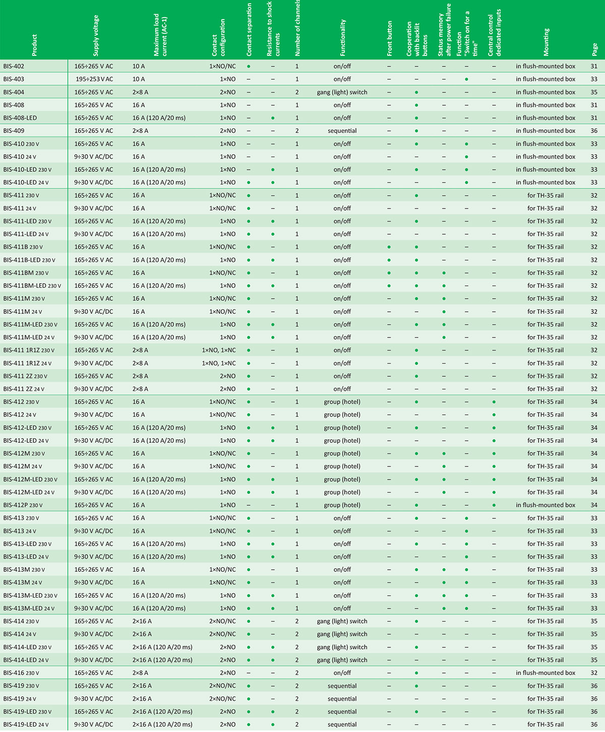
Power table

The above data are indicative and will heavily depend on the design of a specific receiver (that is especially important for LED bulbs, energy-saving lamps, electronic transformers and pulse power supply units), switching frequency and operating conditions.
Tips
Illuminated buttons
If too many illuminated buttons are connected, the lighting may switch on spontaneously or switch on permanently Maximum load current The contact current given in the technical data is the maximum value and may be subject to restrictions – more information. If the information provided indicates that the relay in the device is insufficient, it is recommended to use an external switching element (e.g. contactor) adapted to switch large surge currents. State memory The relay does not have a “memory” of the contact position. This means that after the power supply is switched on, the relay contact will always remain in the off state.