
PurposeUSM is used to cut off, in the event of a fire or failure of water installations, all water receivers, except for fire protection devices. Designed to solve two independent problems, the first of which results from the danger posed by fire, and the second results from the threats posed by water.
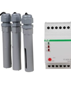
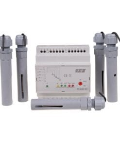
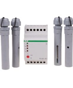
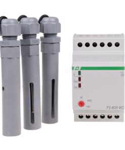
VersionsUSM H – dedicated to detecting emergency conditions and cutting off the power supply to water and “co” installations.USM O – designed to support hydrant installations. It is used to cut off the supply of utility water to the facility so that the hydrant installation in the building where the fire occurred is operational. Can be combined with USM H.USM I – designed for machines and devices. USM in all versions can also supply and cut off media remotely (cooperation with any type of monitoring) and send a return signal about the status of the solenoid valve. System elements: probes (installed in bathrooms, kitchens, toilets, boiler rooms, etc.) used to detect moisture: switchboard and SAM 01 controller, dedicated EZ solenoid valve up to 2” for 12V DC with GW or with additional flanges, ROP type switches or pull cord switch, solenoid valve filter (one filter for 1 solenoid valve) and appropriately sized screw connections, 12V 1.3Ah battery (must be replaced after 3 years), C 1A to 2A installation switch (depending on the number of e-valves), pressure switch (pressure switch in the central heating system “co”), double button (green – on/red – off the solenoid valve)
Example applicationsUSM H 1 – application for detached or terraced houses with probes. References: USM H 341/ USM H 101/ USM H 342/ USM H 102.
USM H 2 – application for detached or terraced houses without probes. Cooperation with the Alarm Control Panel. References: USM H 341 SAT/ USM H 101 SAT/ USM H 342 SAT/ USM H 102 SAT.
USM O 1 – application for buildings with a hydrant installation without probes. Cooperation with the Fire Control Panel. The reference will be created for the needs of specific facilities.
USM O 2 – application for buildings with a hydrant installation without probes. Cooperation with a ROP switch (NC) or/and with a pull switch mounted in the hydrant box (NC). The reference will be created for the needs of specific facilities.
SAM-01 controllerIt is equipped with a panel with indicators that allow monitoring of the e-valve status and the current humidity level on the probes. It also allows you to set the alarm sensitivity and delay time from the moment the alarm level is exceeded to the closing of the e-valves. This solution prevents water cut-off situations in the case of, for example, floor cleaning. The system is equipped with: measuring IN (moisture detection probes and “co” pressure switch), IN for external control, alarm OUT, executive OUT (pulse solenoid valves).
SAM-01 controller
POWER SUPPLY To ensure system autonomy > 24 hours, the SAM 01 controller must be powered simultaneously from two sources: Main power supply – 230V AC terminals 1 – 3 is used to power the SAM 01 controller from which the 12V / 1.3 Ah battery is charged. Backup power supply – 12V / 1.3Ah battery terminals 5 – 6. When the 230V power supply fails, the battery takes over its function. If the battery voltage drops below 10.5V, the controller will close the e-valve and go into standby mode, in which the e-valve remains closed and all controller functions are frozen. The standby state is signaled by a short flash of the LED indicator (red – 230V / 12V power supply) repeated every 10-15 seconds. Return to full functionality is only possible after restoring the correct power supply to the controller and pressing the green button. PROBES – used to detect failures in water installations. Probes should be placed in places particularly susceptible to moisture. There are 2 types of probes available: residential and for boiler rooms. Probes are connected in parallel, mounted approx. 15 mm above the floor. ELECTRONIC VALVES (dedicated to work with the SAM01 12V DC controller). They are tested automatically once a month and dedicated as equipment for the USM system. It is possible to control several e-valves simultaneously, depending on the power of the coils. The polarity of e-valves is in applications. Other polarity will reverse the function of the system.
Alarm outputs Emergency state 1 – probes have detected moisture. Emergency state 2 – signaling activation by providing an external signal. The buttons on the front panel of the SAM 01 controller are needed when probes are used and are only used to program the sensitivity in the probe installation and the delay in controller operation as a result of probe moisture. The alarm in the controller may be triggered for the following reasons: 1) Exceeding the set moisture sensitivity level in the vicinity of the sensors. The controller starts counting the time until the failure is reported. This state is signaled by the alarm diode flashing. After the set delay time has elapsed, the valve is closed and the controller signals the flooding alarm (alarm diode). 2) or a signal from an external source (fire protection control panel, alarm panel, pressure switch, fire switch or cable switch). Applying a signal causes the e-valve to close immediately and the alarm is reported by the alarm diode flashing on – dimmed). The e-valve can only be reopened after the causes of the alarm have been removed and the green button has been switched on. Advantages * limits pressure drops and improves the efficiency of fire extinguishing systems by cutting off utility water; * does not need to have CBNOP and ITB certification for installation in any building; * is insensitive to 230V power failure, as it has its own emergency power supply; * can be controlled manually or from monitoring. Works with wireless systems; * tests itself automatically once a month; * can be controlled by sending signals via the Internet, Ethernet, GSM, etc.; * is a specially selected system for the customer’s needs in the form of a ready-to-install product, adapted to the specific needs of the facility; * works with moisture detection probes.